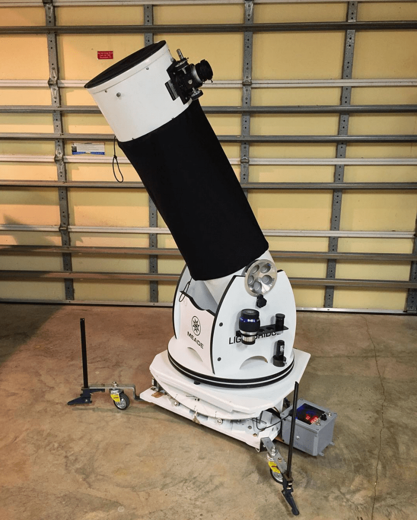
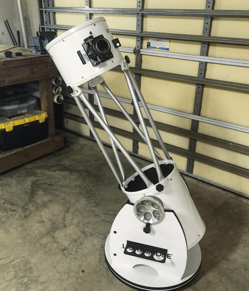
I purchased an improperly-modified reflector telescope on Craigslist for a bargain. It was an excellent telescope; a 10″ mirror collects an enormous amount of light. But it needed work, and it needed a precision motorized platform to be able to capture long-exposure images of the night sky.
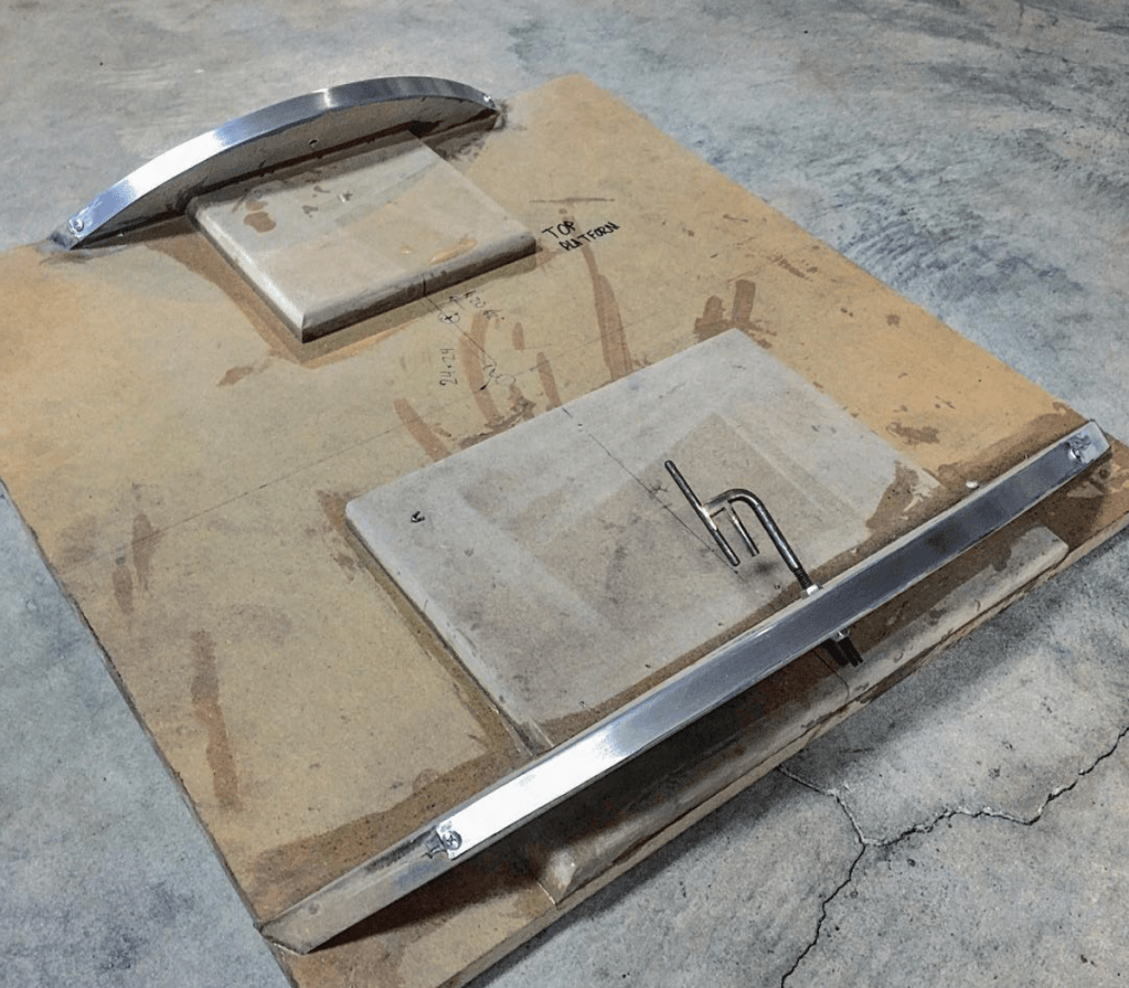
After fixing its previous issues and confirming that the mirrors were unharmed, I built the below platform, which was carefully-designed to rotate about an inclined axis that is parallel with the earth’s rotational axis.
Tracking the Stars: “Poncet-” or Equatorial-Platforms
On a budget, it’s difficult to obtain both the benefits of a large-mirrored telescope (large aperture and light-gathering ability) and that of a smaller astrograph (ability to use smaller and more affordable motorized Newtonian mounts).
A common solution is to build a platform that rotates about an inclined axis. This is not an easy task, as nearly every dimension is calculated from a model, and many are critical. Each platform is built to match the latitude where the photos are being captured:
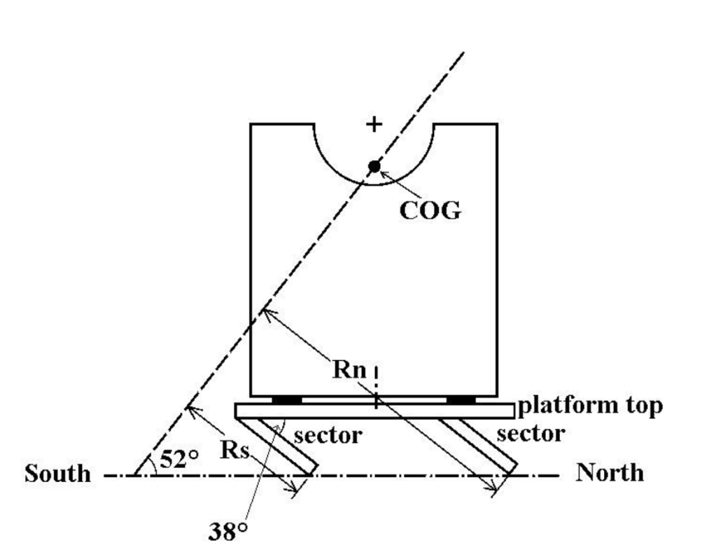
The dimensions are chosen so that the axis of rotation is coincident or slightly below the CoG, so *very little* work is required to rotate the telescope.
The telescope’s CoG was determined by estimation of the masses of the major components.
Early Progress
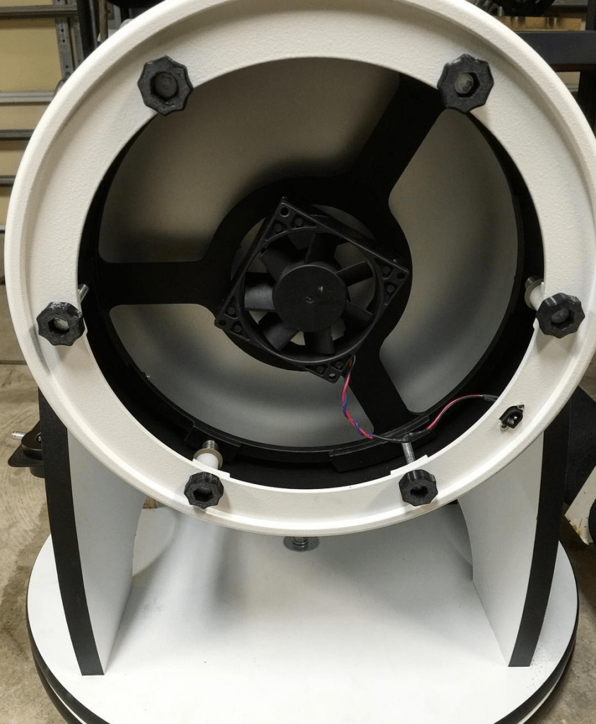
The previous owner had purchased a focuser that did not fit well, and hacked into the upper ring to install it. Their goal was apparently to shift the focal plane so that it was coplanar with the camera’s sensor. It may have helped, but not enough for the Canon 6D I intended to use. I took the focuser off, fixed the sheet metal, and sealed the gaps with permanent black neoprene adhesive foam from McMaster-Carr.
Distilled water and lab-grade sterile slide wipes were used to clean the primary and secondary mirrors.
Constructing & Mechanizing the Platform
The platform build itself went through several revisions. I struggled with eliminating the numerous sources of error present in a machine intended to rotate a heavy object at rates that must vary less than 1-2 arcseconds per minute. This value describes the variance (error) in rate allowed, on top of the fixed 0.25 degree-per-minute rotation required to offset the earth’s rotation (known as the sidereal rate).
Early Drive Mechanism
The fork-and-pin system proved to have too many sources of error, but I stuck with the design for a while to eliminate as much remaining error as I could.
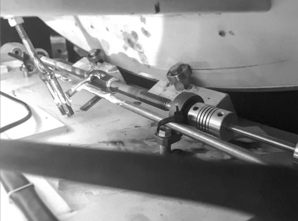
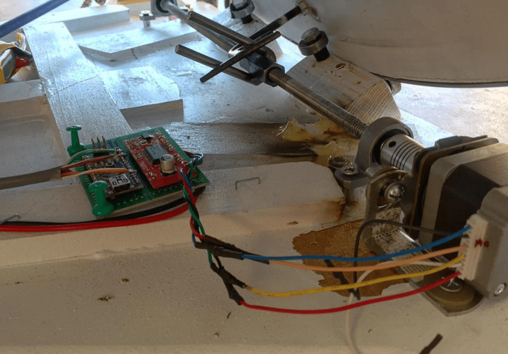
Improvements to Drive Mechanism: Threadless Ballscrews
For reasons I’d learn later, UNC threaded rod does not make a good leadscrew. I created a threadless ballscrew using 6 small ball bearings and an 8mm chromed linear rail. In this case, I viewed it as a superior solution: near-zero backlash, improved rigidity of the rotating rod, and an infinitely available set of pitches.
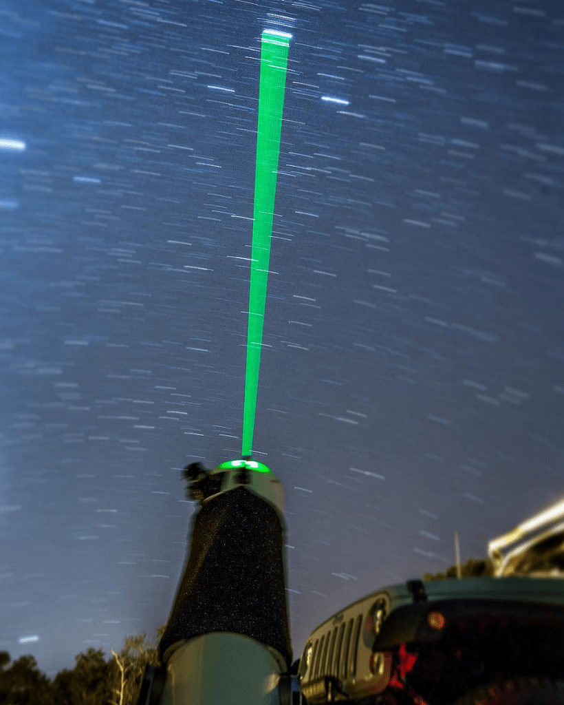
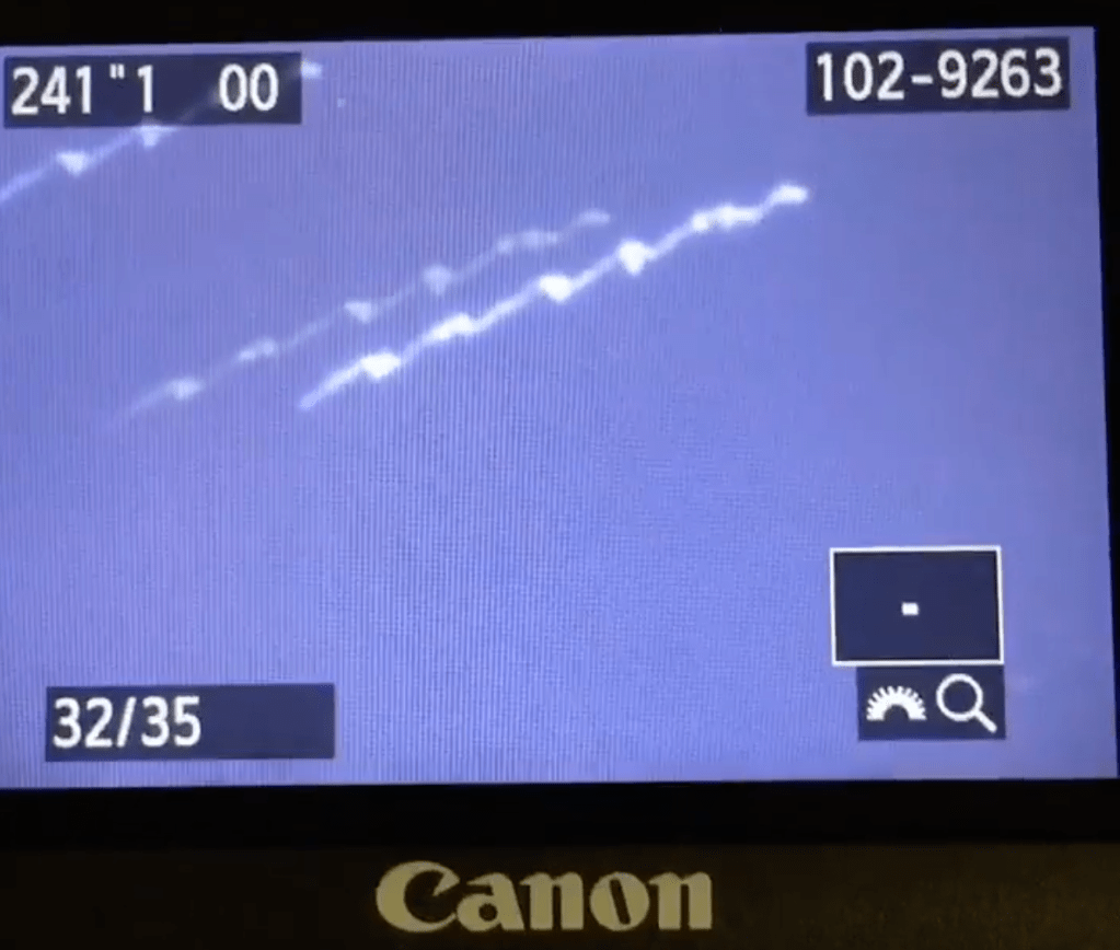
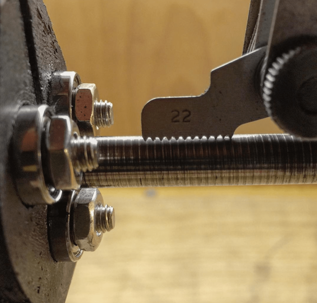
To adjust for inconsistencies in desired pitch and effective pitch, I simply added a potentiometer to “trim” the step-rate sent to the stepper driver. The analog value from the potentiometer was mapped to a range that was added or subtracted to the fixed, hard-coded steps/min value. I chose that particular value by calculating it from the apparent pitch, shown in photo #3. A thread pitch gage and light grease found that the apparent pitch was equivalent to approximately 22 TPI.
Besides (ideally) zero backlash, minimal wear, and minimal rotational resistance, threadless ballscrews have axial load capacities much higher than I expected.
This is seemingly due to both contact materials (OD race of the bearing, and the inner shaft) being hardened, resulting in extreme rolling-contact forces, and subsequently, high frictional forces.
Finalizing the Design
Countless modifications have been omitted from this project description. Many late nights were spent measuring run-out in thousandths of an inch with dial test indicators, taking test images to pinpoint periodic error, trimming step-rates, adjusting collimation, and more.
I eventually chose to keep the threadless ballscrew drive system. The ballnut was designed with a protruding threaded rod, which held a nylon roller. This roller pressed against a rigid stainless rod affixed to the upper platform, and drove it about the desired axis.

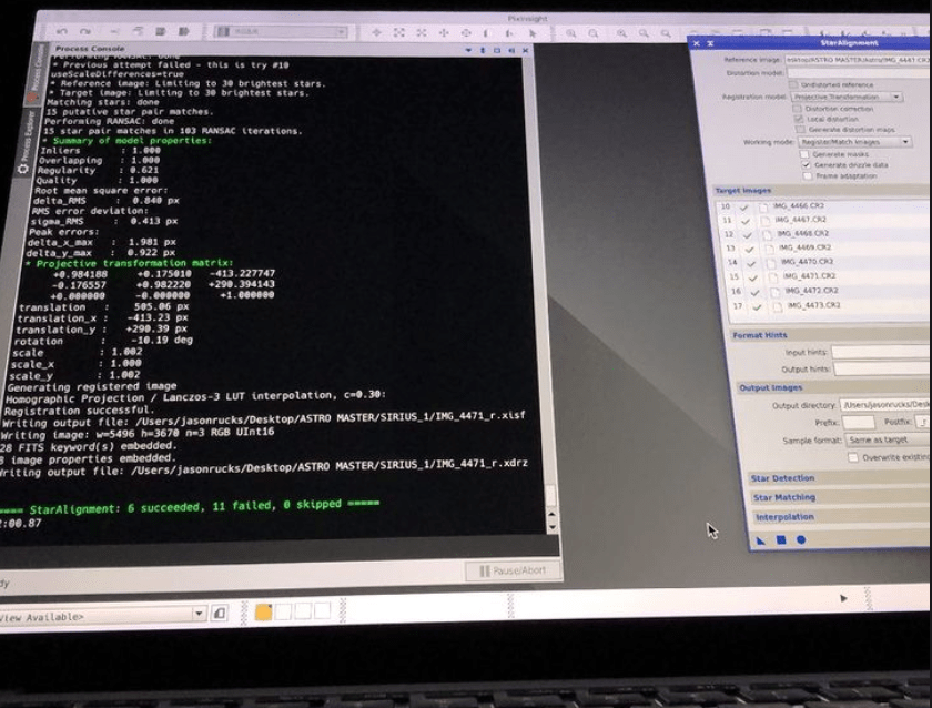
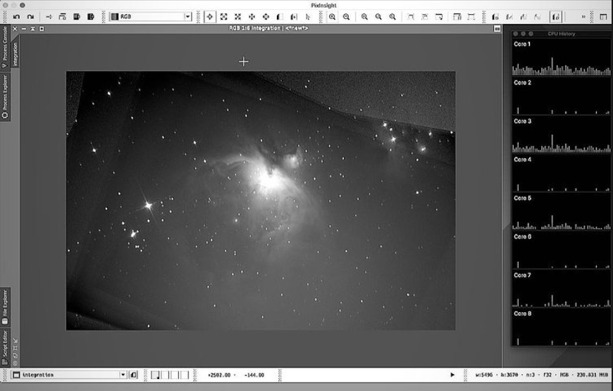
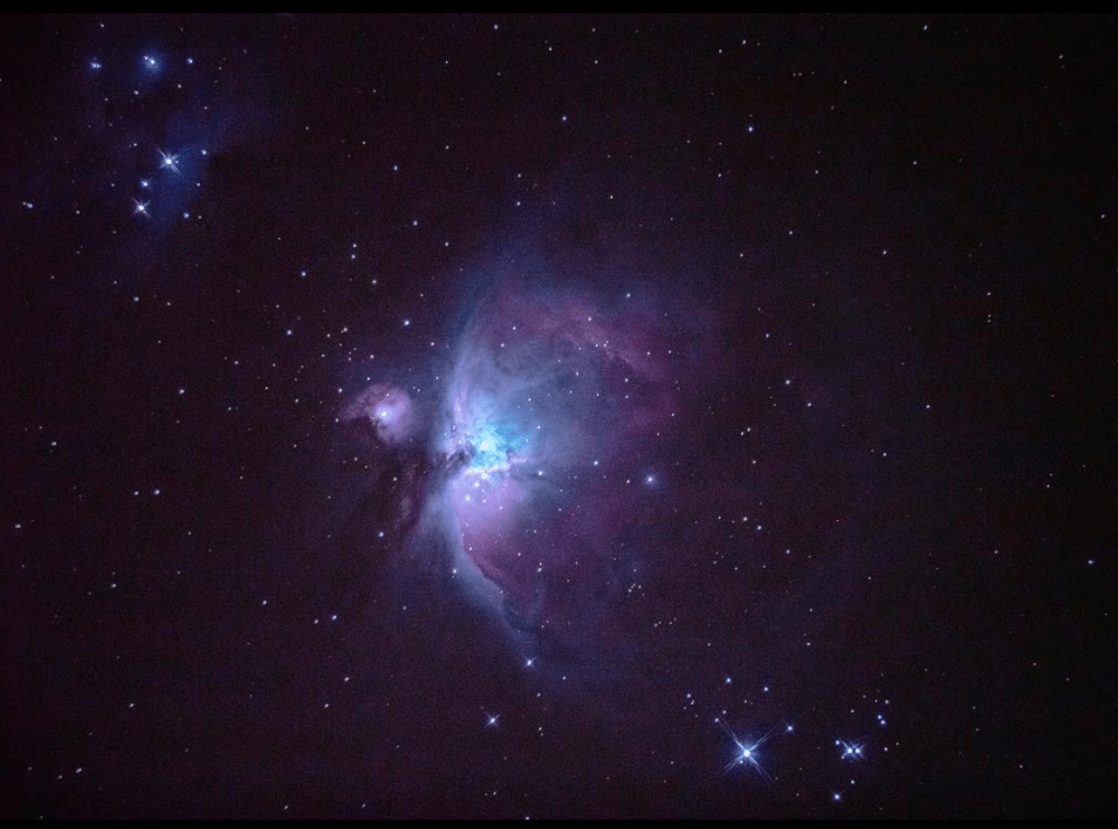
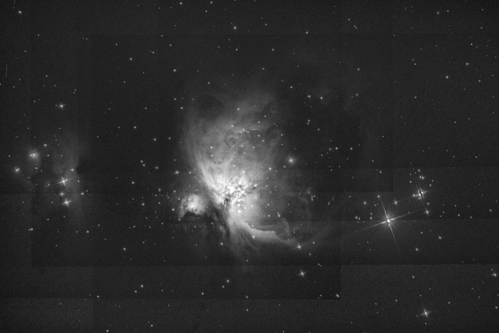
Computational Astrophotography
Stunning photos of celestial objects are possible with careful processing. While all of the photos below do not take advantage of this process, the deep-sky-objects and nebulae nearly require such processing. Essentially, a number of photographs are taken of the same object, and the data these images contain is integrated, summing the information stored in each coordinate to provide a higher depth of information.