Explanation & Objective
Astrophotography often requires long-exposure imaging. The shutter may be open for many seconds, to several minutes. However, while celestial objects do not move much over this amount of time, the earth does. The earth rotates at the sidereal rate of 0.25 degrees/minute.
Imaging without compensating for this rotation results in stars leaving light trails, rather than individual points of light. The barn-door tracker cancels the earth’s rotation out by rotating in an opposite direction, about an axis parallel to the earth’s axis of rotation.
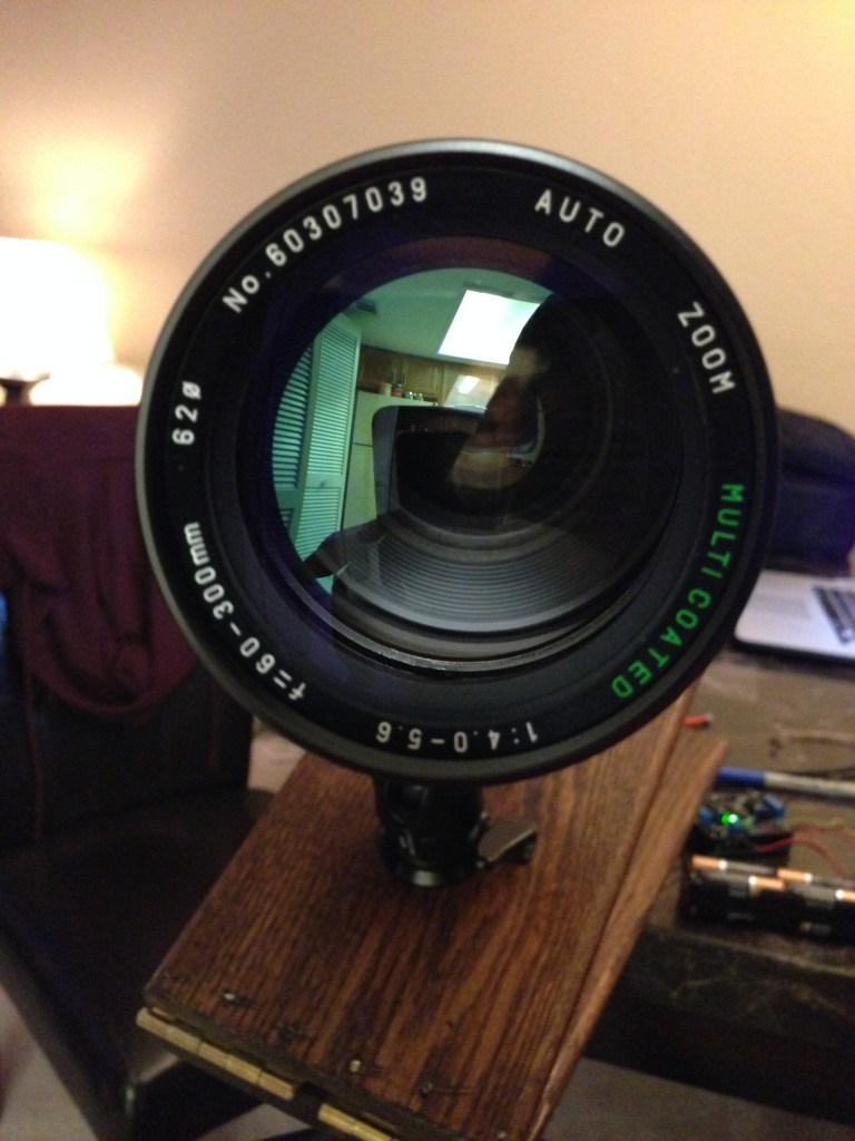
The theory is identical to the one used in my equatorial platform, but since DSLR’s are much lighter than telescopes, building a barn-door tracker is usually best. Additionally, a Scotch Mount can be used at different latitudes, as the inclination is set with the angle that the hinge axis makes with level ground (and again, equal to the latitude where the imaging is taking place).
Construction
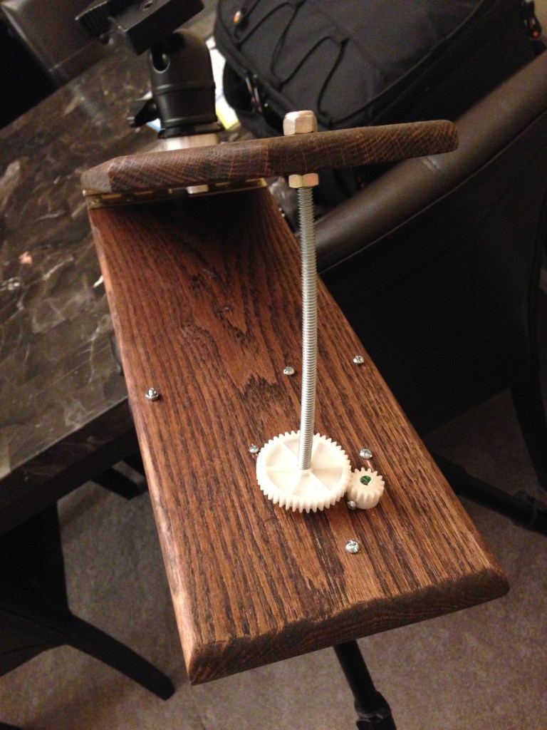
There are a few different styles of tracker, with most differences occurring in the way the camera is driven about the axis. I chose to use a curved threaded rod as a leadscrew, because there is zero tracking error with this method. A straight threaded rod, for example, would incur trigonometric error at the limits of travel, and would have a nonzero angular acceleration.
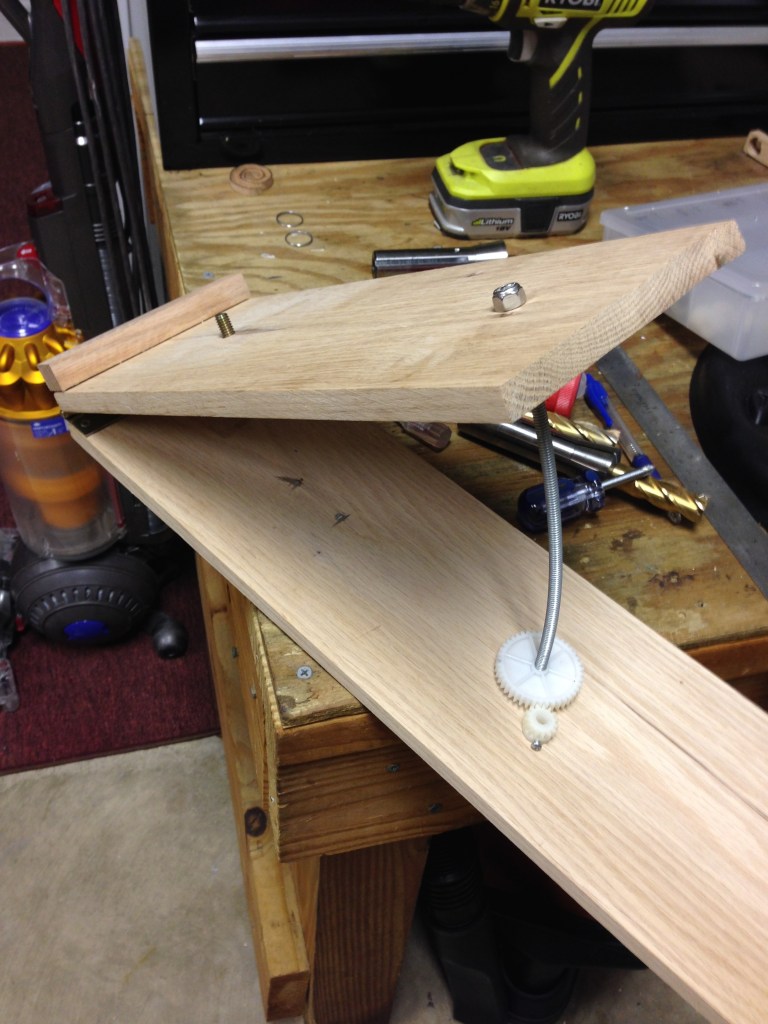
Then, I bent the rod carefully, until it approximated that curve. I began with a much longer length than needed, and cut out only the section of threaded rod that appeared to have the best curve fit.

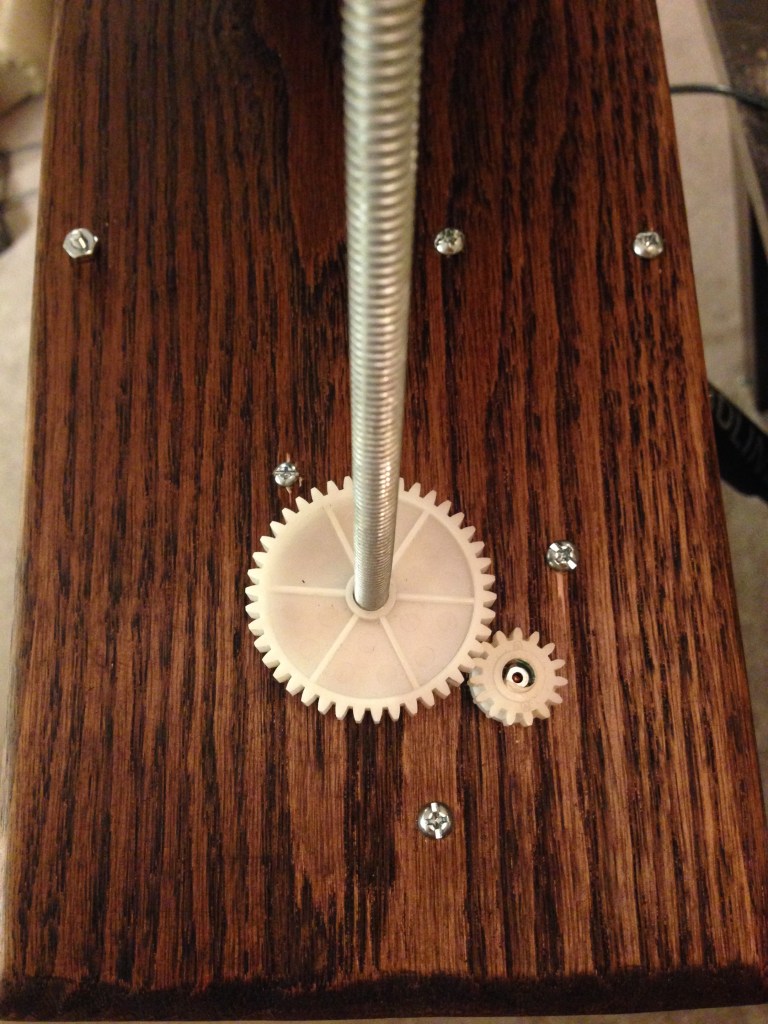
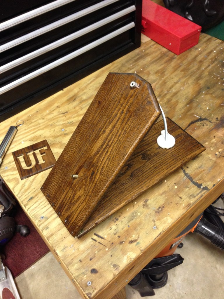
Decorative Stain & Drive System

Motorizing the Mount
Quick calculations using the thread pitch, sidereal rate, leadscrew radius, and gear reduction provided the step-rate needed.
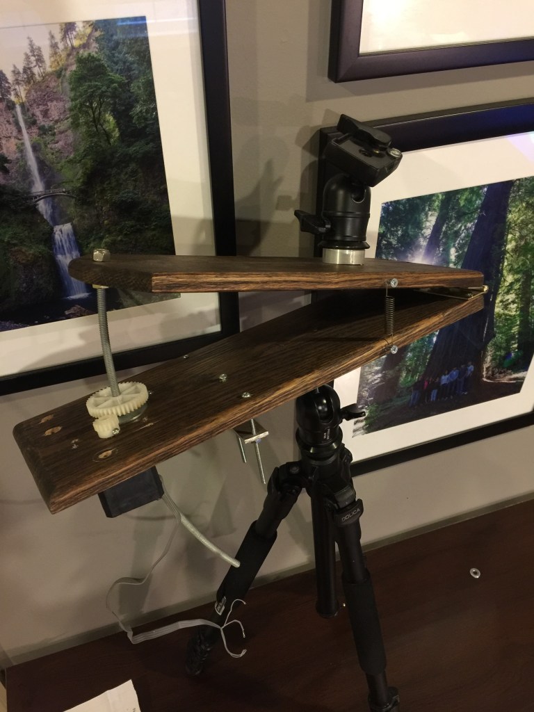
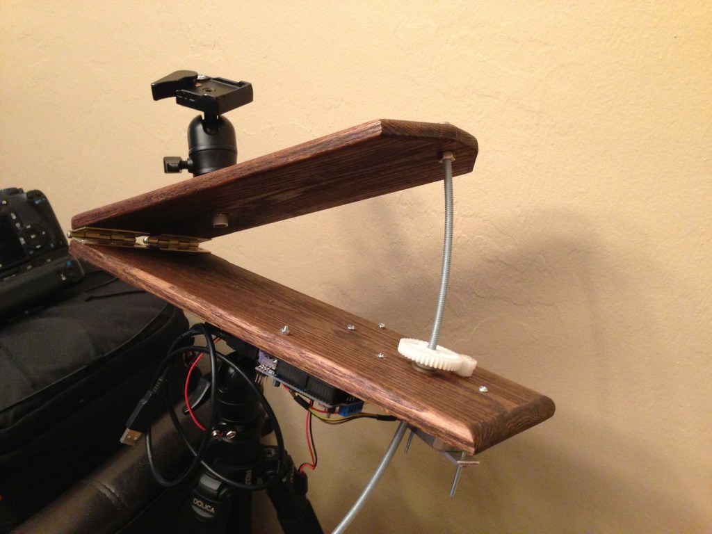
The Finished Barn-Door Tracker
Aside from occasional electrical issues with the stepper driver, the mechanical-side of the tracker performed flawlessly. To use the tracker, the hinge axis is pointed toward Polaris (the North Star). This places the hinge axis parallel to the earth’s rotational axis, because Polaris is nearly coincident with the earth’s axis of rotation, and at an effectively infinite distance from the earth.